

Adding Adjustable Output Trim to the Mean Well NID65-5
Introduction
While working on a project requiring a reasonably high-current 5 V supply, we came across the Mean Well NID65-5.
The NID65 is a compact non-isolated DC/DC converter accepting a wide DC input and, in the case of the NID65-5, providing a regulated 5 V output at up to 6.5 A.
For our application the supply was being used to power a Raspberry Pi and associated hardware over a length of cable. At these relatively low voltages even a small amount of cable resistance becomes significant, with a drop of only 0.2 V representing 4% of the entire supply voltage.
What we really wanted was the ability to increase the NID65-5 slightly from its standard 5.0 V output to somewhere around 5.2 V.
Interestingly, the Mean Well datasheet shows Pin 10 as "Trim (optional)", but provides no further information explaining how the pin is used.
Finding the Trim Circuit
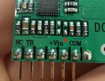
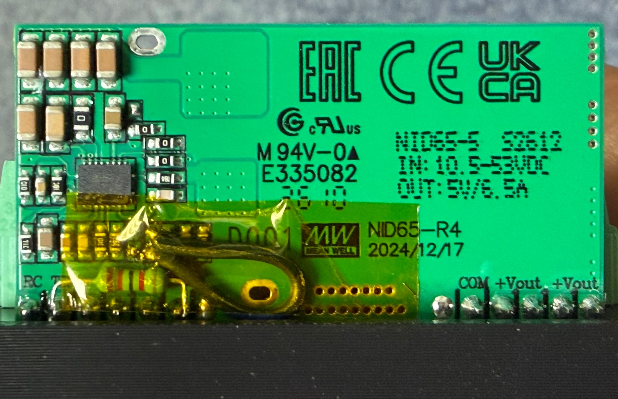
Looking closely at the NID65-5 PCB revealed that the Trim pin was actually connected to the circuit board, despite the trim function not being populated on our version.
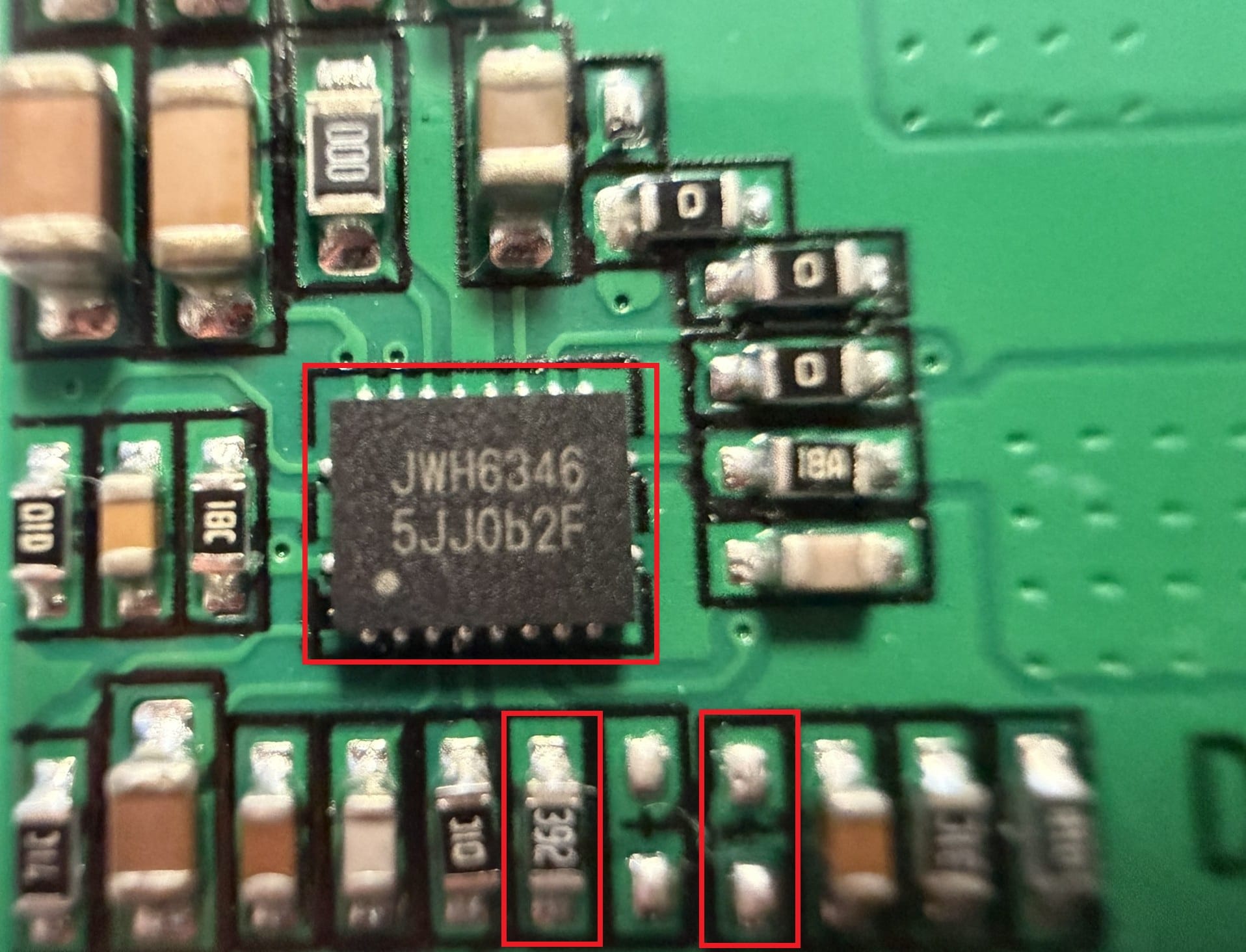
Following the PCB trace from Pin 10 led to an empty SMD resistor position close to the converter's feedback circuitry.
The lower pad of this unpopulated resistor position had direct continuity to the TR pin.
The upper pad connected into the regulator feedback network.
This immediately suggested that Mean Well had designed the PCB to support adjustable-output versions of the converter, with a resistor simply omitted from the standard fixed-output model.
Reverse Engineering the Feedback Network
Some measurements with the converter powered down helped identify what the surrounding components were doing.
From the feedback node we measured approximately:
- 3.8 kΩ to COM
- 19.25 kΩ to VOUT
We then traced the 3.8 kΩ path and found that it went through a resistor marked 392, or nominally 3.9 kΩ, directly to COM.
This gave us a feedback network approximately equivalent to:
                  ~19.25k
VOUT ────────────/\/\/\/────┐
                             │
                             ├──── Feedback
                             │
COM ─────────────/\/\/\/─────┘
                   3.9k
                             │
                             └── Empty resistor ── TR
The measurements also produce a calculated feedback voltage of around 0.84 V at a 5 V output, which is entirely reasonable for the regulator circuit being used.
How the Modification Works
To increase the output voltage we need to reduce the effective resistance between the feedback node and COM very slightly.
Rather than replacing the existing 3.9 kΩ resistor, the unused Trim connection gives us a much neater way to do this.
Adding additional resistance between the feedback node and COM places it electrically in parallel with the existing 3.9 kΩ feedback resistor.
A lower effective resistance causes the regulator to increase its output voltage until the feedback voltage once again reaches its internal reference.
Based on the values measured on our converter, the approximate additional resistance required is:
| Target output | Additional resistance FB → COM |
|---|---|
| 5.0 V | Open circuit |
| 5.1 V | ~162 kΩ |
| 5.2 V | ~81 kΩ |
| 5.3 V | ~54 kΩ |
| 5.4 V | ~41 kΩ |
| 5.5 V | ~32–33 kΩ |
These values are calculated from measurements taken on our particular NID65-5 rather than official Mean Well trim data, so the actual voltage should always be checked with a multimeter.
Making It Adjustable
Rather than selecting a fixed voltage, we wanted a simple way to fine-tune the output between approximately 5.0 and 5.5 V.
A convenient solution is to use:
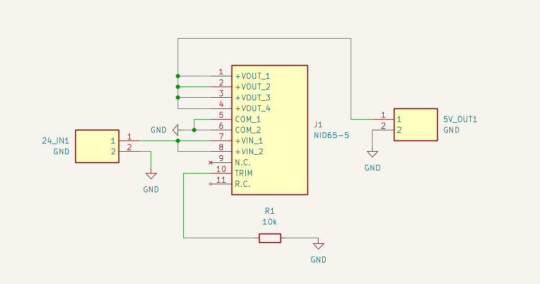
- 32 kΩ fixed resistor (installed in place of the original trim component)
The 32 kΩ resistor provides a sensible upper limit to the adjustment range while still allowing the output to be tuned upward as required.
The circuit becomes:
Feedback
   │
   ├──────── 3.9k ───────── COM
   │
   └── 32k ─── TR ─── COM
At the chosen value, the output can be adjusted to around 5.2 V, which suits our application by compensating for cable losses without overdriving the load.
Modifying the NID65-5
The modification itself is quite simple, but our implementation was shaped by practical constraints.
Because we did not have access to an SMT rework station, we first used a bodge wire to bridge the TR resistor pad. We then soldered a full-sized resistor between COM and TR, allowing us to validate the circuit behaviour before committing to a cleaner design.
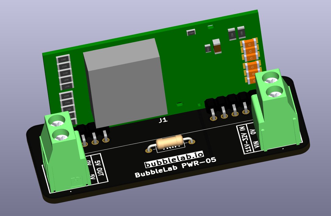
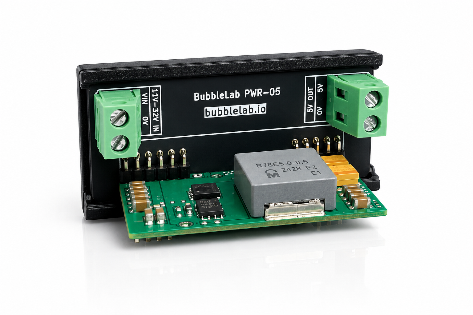
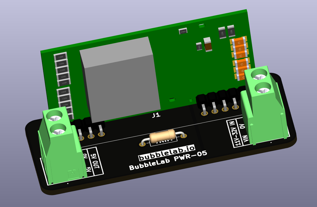
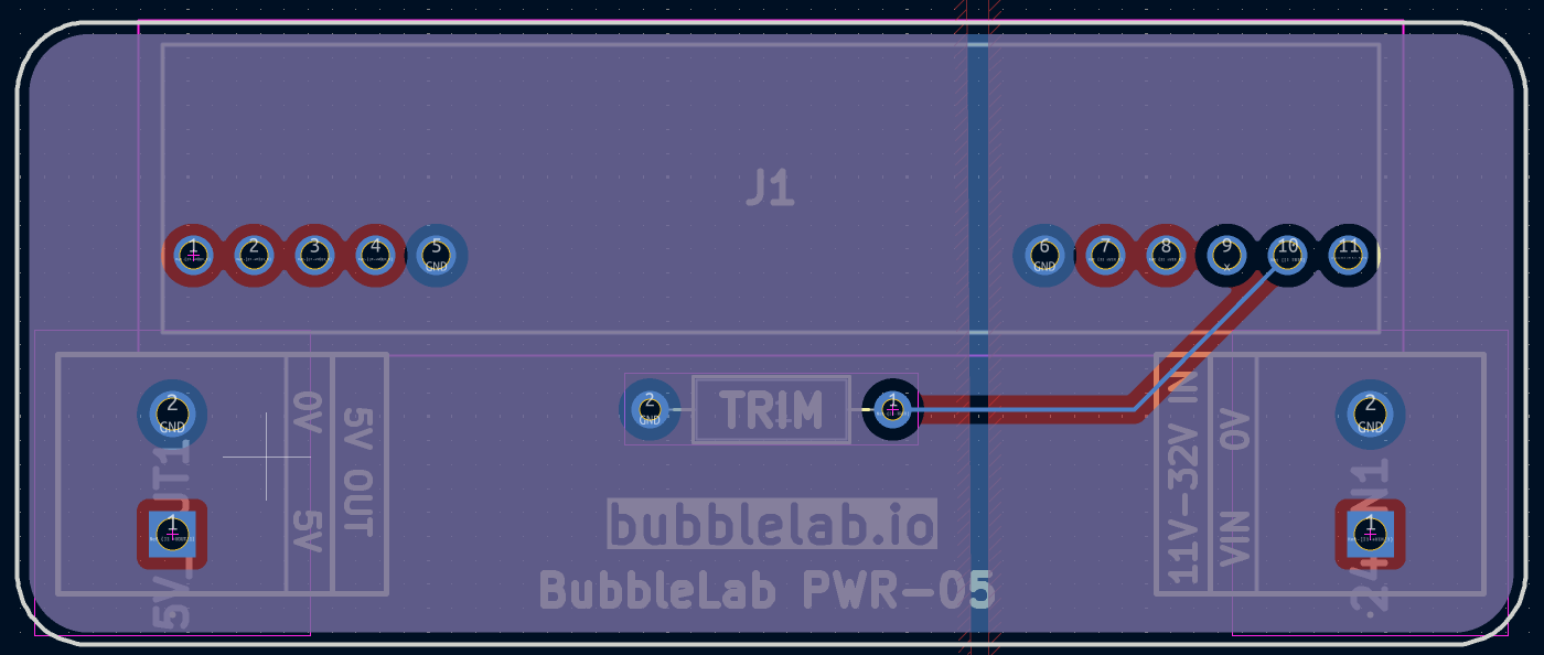
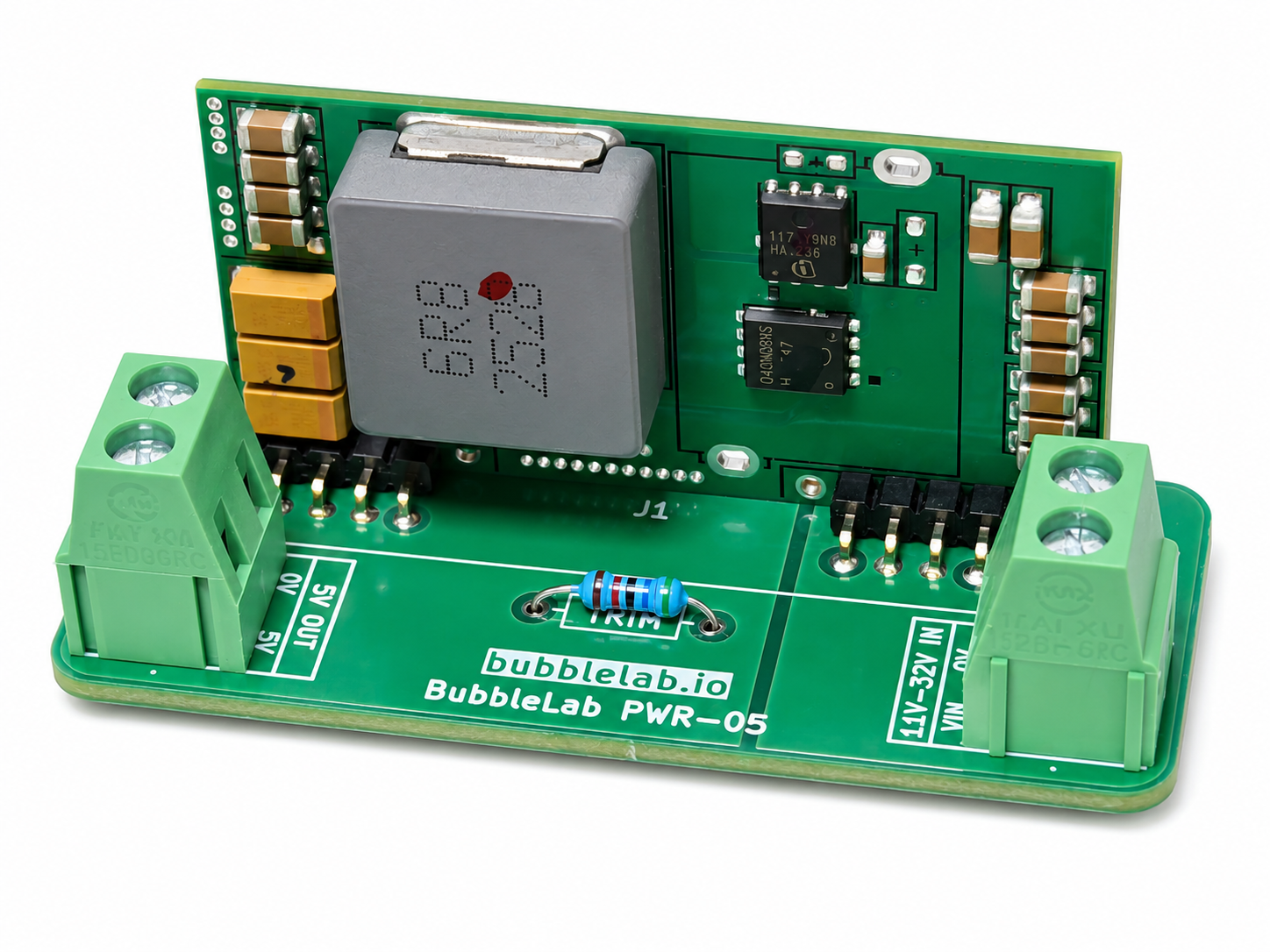
After confirming correct operation, we designed a dedicated PCB that holds a single full-sized TRIM resistor footprint, eliminating the need for bodge wiring entirely. In the final design, only the small SMT pads on the NID65 need to be bridged to the carrier board.
First Power-Up
We strongly recommend testing the modified converter before connecting it to any valuable load.
Power the NID65 from a current-limited bench supply and leave the 5 V output unloaded.
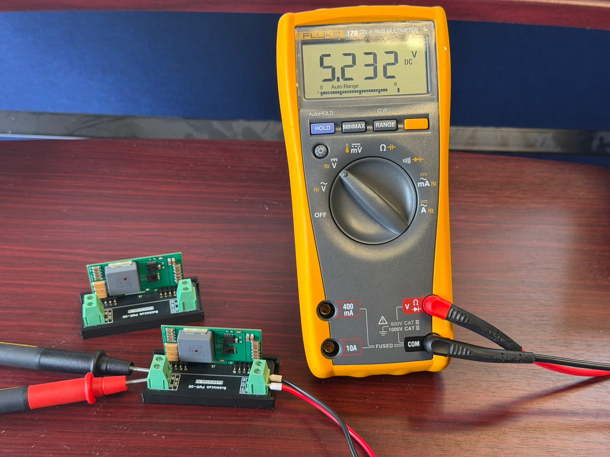
Connect a multimeter directly across VOUT and COM.
With the installed 32 kΩ resistor, the converter should start close to its original 5 V output, with the ability to be trimmed upward.
Slowly adjust the effective resistance while watching the output voltage.
The voltage should rise progressively towards approximately 5.2 V as the resistance is reduced.
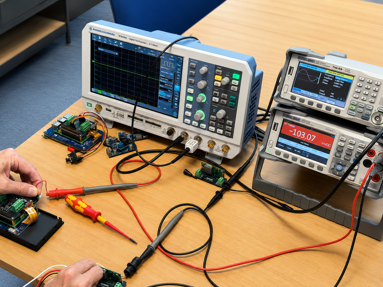
Once the desired voltage has been set, cycle the input power several times and confirm that the output returns to the same voltage each time.
We eventually set ours to approximately 5.2 V, giving us a little extra allowance for voltage drop through the wiring without operating the Raspberry Pi from an unnecessarily high supply voltage.
Output Power Is Important
There is an important point worth mentioning with the NID65-5.
Despite the series being called the NID65, the 5 V version is officially rated at 32.5 W, with a maximum output current of 6.5 A.
Increasing the voltage does not magically increase the power capability of the converter.
For example:
5.0 V × 6.5 A = 32.5 WAt 5.5 V, drawing the same 6.5 A would require:
5.5 V × 6.5 A = 35.75 Wwhich exceeds the rated output power.
If operating at 5.5 V, the theoretical current corresponding to the original 32.5 W rating is therefore approximately 5.9 A.
For our application the adjustment is primarily intended to compensate for wiring losses rather than extract additional power from the converter.
Why Not Simply Replace the 3.9 kΩ Resistor?
It would be possible to change the existing 3.9 kΩ feedback resistor directly.
However, using the provided TR connection has several advantages.
The original feedback network remains untouched, adjustment can be made externally, and the fixed 32 kΩ resistor prevents the feedback node accidentally being pulled directly to COM.
It also appears to use the PCB exactly as Mean Well intended when they designed the optional Trim connection.
Important Warning
This modification is not documented or supported by Mean Well.
Although Pin 10 is officially identified as Trim (optional) in the NID65 datasheet, Mean Well does not publish the external resistor values or adjustment range for the NID65-5.
The values above were obtained by tracing and measuring our own unit.
Component values or PCB revisions could change between production versions, so anyone attempting the same modification should verify the feedback circuit on their own converter before fitting components.
Modifying the converter may also invalidate its warranty and potentially affects the manufacturer's original electrical, EMC and safety specifications.
Never connect TR directly to COM without a suitable resistance in series. Doing so could cause the regulator to command a substantially higher output voltage.
Conclusion
The NID65-5 turned out to be more versatile than its documentation initially suggested.
Mean Well had already provided the connection required for output trimming; on our fixed 5 V version the necessary resistor was simply not populated.
By tracing the feedback circuit we were able to use this unused connection to provide a practical adjustable output of approximately 5.0–5.2 V using a single resistor solution, validated initially with a bodge-wire prototype and later refined into a dedicated PCB design.
For installations involving high-current 5 V loads this is particularly useful, as even relatively heavy cabling can produce noticeable voltage drop over distance.
In our case an output of around 5.2 V gives enough headroom to compensate for those losses while retaining the compact size and high efficiency that made the NID65-5 attractive in the first place.


Comments ()